Below are some schematics out of the original notebook we used while developing the system.
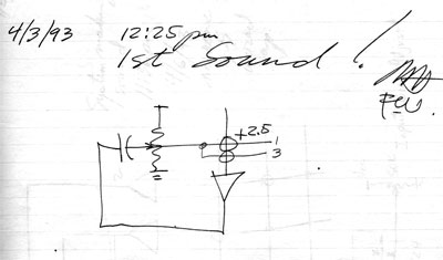
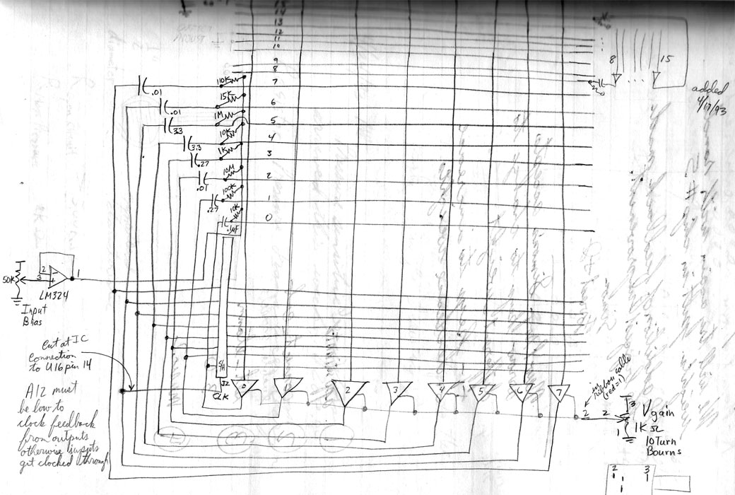
The schematic below shows the basic oscillator circuit used for most of the neurons in Chip 3. It is a simple relaxation oscillator with the frequency set by the values of the resistor and capacitor (RC time constant). The triangle represents the neuron amplifier and the column represents its input which is a summing node which sums weighted inputs from the RC circuits. The circles represent weights. In the drawing below both inputs 1 and 3 are connected to the RC circuit and contribute to the sum of weighted inputs. This circuit uses positive feedback. The output is forever trying to force its input to the same state as its output but because it is AC coupled to the input via the capacitor it can only achieve its goal momentarily until the resistor pulls the input back toward the amplifier's Vin = Vout point which is the middle of its linear operating range. As the amplifier comes out of saturation the out put starts responding to the input again and couples back through the capacitor its amplified change to the input. The input shift quickly drives the amplifier to saturation again but, this time to the other rail and the process starts over again. Next the resistors again pull the input back to the middle of its linear operating range.
The oscillations are gain dependent and their frequency depends on the values of the resistors and capacitors used in the circuits which are off chip. The gain of all the neurons can be controlled simultaneously using the Vgain control on the control box. the loop gain for particular neurons and inputs can be controlled by setting the weight values in the ETANN array. Weights are available on chip to couple any output to any input which is what makes these oscillator circuits so complex. They are highly cross coupled and as a result the oscillation waveforms become very complex, often not repeating for very long periods of time.
Because thermal noise on the neuron amplifier columns is present and the amplifiers are high gain and biased near their maximum gain points there is an element of the oscillations which is totally random, a result of the Brownian motion of populations of electrons in the amplifier circuits. Digital synthesizer circuits do not have this sensitivity and are not capable of this behavior. Who wants their computer to give answers dependent on the temperature in the room and the time of the question. Musicians into complete control of their instrument won't like this box. Its for artists like John Cage and David Tudor who search for novelty unbiased by their own brains.
The Neurons generate a sum of weighted inputs as shown below. The neuron amplifier has a saturating transfer characteristic called a sigmoid. It is linear in mid range and saturates gradually near its extremes. A sum of weighted inputs in also referred to as a "dot product".
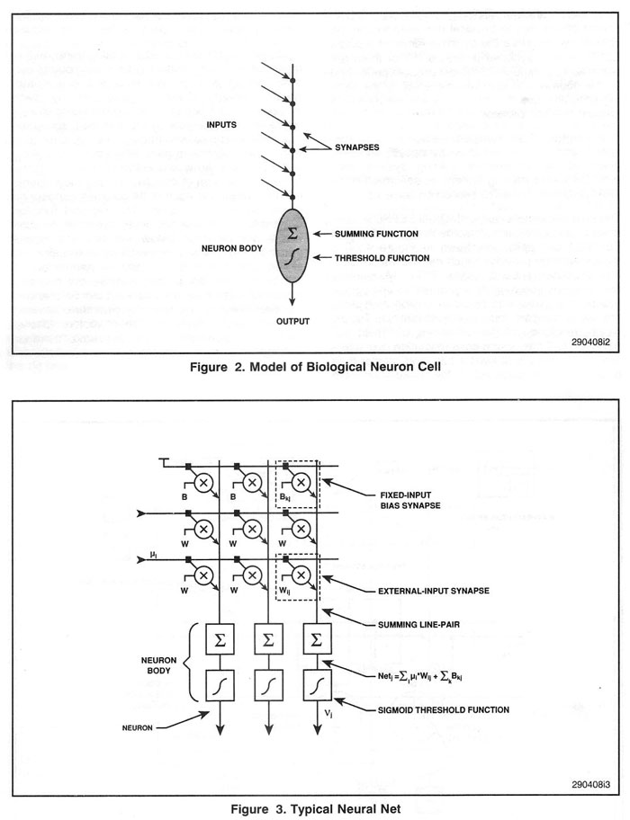
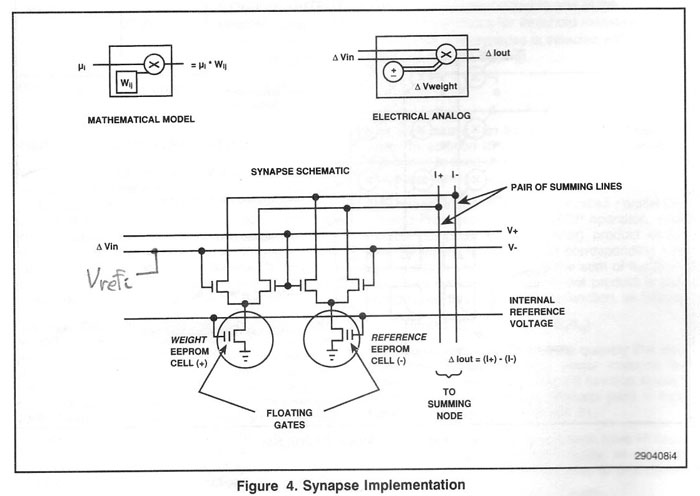
The input amplifiers are basically unity gain buffers. The synapses however provide gain as they consist of a multiplier and a non-volatile stored weight. They take a differential voltage as input and output a differential current which is summed by the physics of currents being drawn from a wire also known as Kichoff's Law.
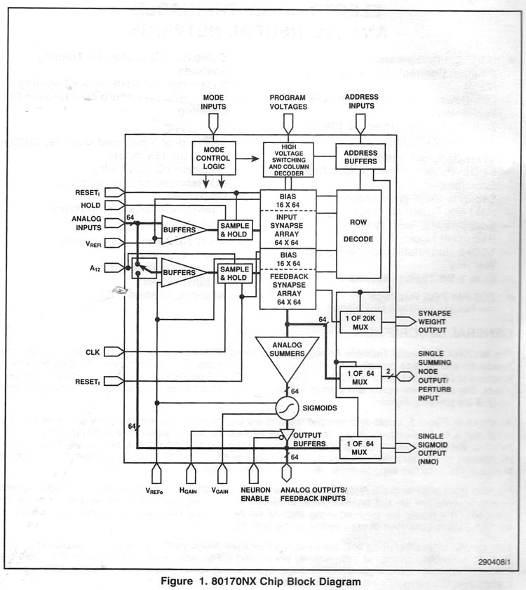
Below is a block diagram of the 8017NX which are the Intel Neural network chips used in MBOXII. The 80170NX is an Electrically Trainable Artificial Neural Network ETANN. This chip is one of very few and is probably the most complex analog VLSI circuit to use analog non-volatile memory elements. The bandwidth of its circuits is in excess of 100KHz which gives it plenty of margin for audio applications. Typical propagation delays from input to output are 2 microseconds.
There are actually two weight arrays on chip which are multiplexed to allow two layer neural networks to be simulated. There is a potentiometer on the control box which allows you to change the clock frequency of the clock which multiplexes the neurons for two layer operation.
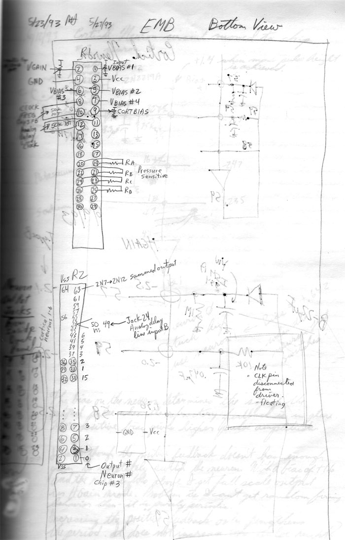
The schematic below shows the general architecture and circuitry associated with chip 3 which we call the oscillator network. It was designed like box I primarily to create oscillations using its very complex and configurable feedback paths. Note that Input biases are actually controllable from the front panel for groups of 4 neurons each not 8 neurons as shown here.
Here is a picture of the front control panel.
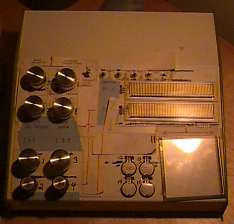
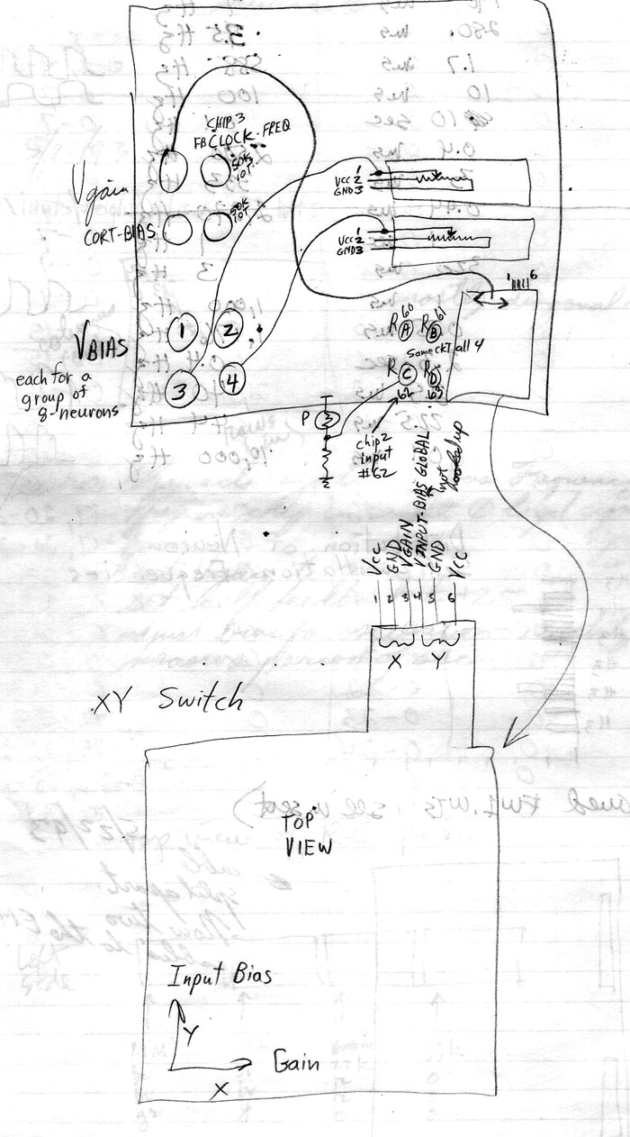
The drawing below shows the front panel of the control box and its connectivity. It has 8 potentiometers on the left and several touch pressure sensitive resistors on the right with different geometries. The pot above number 2 is now used for control of the analog delay line clock frequency which will be described later along with the functions of the other pots.
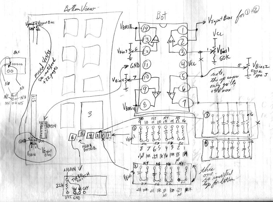
The schematic below shows how 4 groups of 4 inputs each of which have a common bias control on the lower front panel of the manual control box. You can also see the specific RC pair values for each neuron. Note each neuron input has a different RC pair producing different tones on each neuron when simple self feedback is all that is used.
Note that the chips and MBOX II also have a high gain mode in which the neuron amplifier gain is very high which results in much sharper sounds and more abrupt spikes. This mode is activated by a push switch above the patch panel.
Pressure sensitive resistors on the front panel are used in parallel with the input bias divider and pull up that voltage toward VCC. They can be useful for introducing short term transients in the oscillations. MBOX II is build from the ETANN Multichip Board or EMB which has sockets for eight 80170NX chips and support circuits. Currently the box has only 3 of the 8 chip sockets used. They are used as follows:
Chip 3 Neuron Oscillators
Chip 2 Cortical Neurons
Chip 5 FFT
The EMB has all the support circuits required for programming the chips and operating them as well as room for prototyping external oscillator circuits.
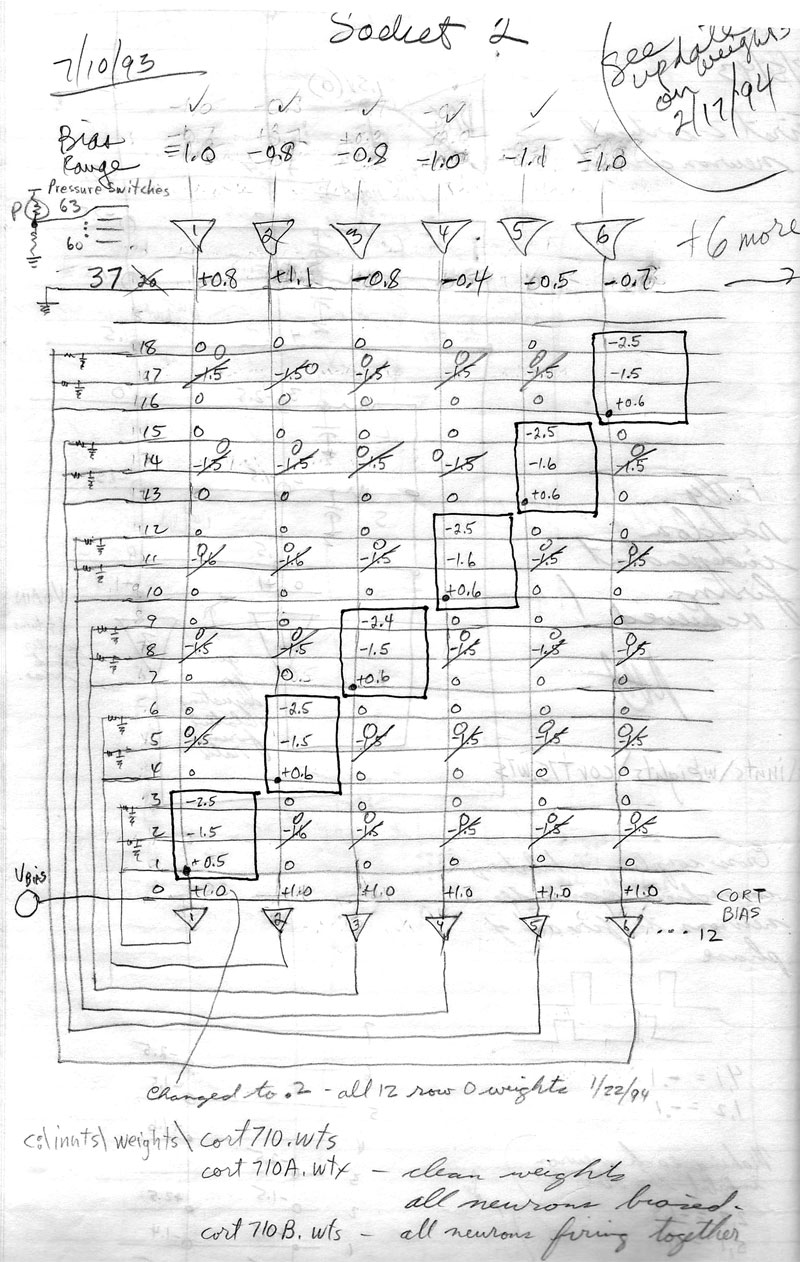
This chip is identical to chip 3 but the circuitry around it is very different. The chip 2 feedback circuits are designed to produce spikes very much like the spikes observed in biological neurons. It has two feedback paths, one fast positive feedback path corresponding to Sodium channels and a slower negative feedback path corresponding to Potassium channels which restores the neuron after a spike occurs. This chip always operates in high gain mode. It has a global bias accessible from the control box that allows the neuron firing threshold to be adjusted. Near threshold the firing of spikes becomes sensitive to thermal noise in the neuron amplifiers as well as spikes from other neurons and inputs external to the MBOX II. Of course the array of 10,000 weights allows any neuron to be interconnected to any other neuron. Fairly quickly though cross couplings change the character of the neural spikes to non-biological like behaviors. Turning up the bias on the cortical neurons causes them to fire more rapidly until they are all firing at their maximum rate.
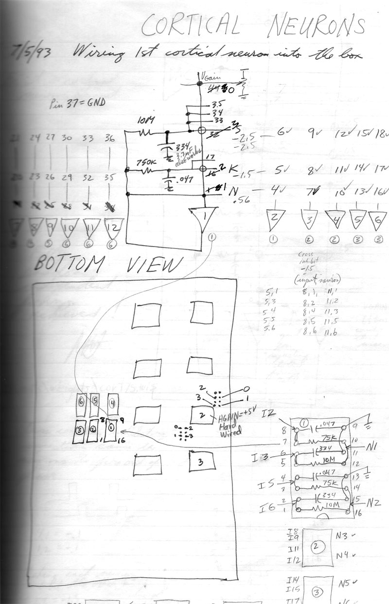
12 neurons on Chip 2 are programmed with feedback for spike like behavior since each neuron requires 3 different feedback connections to itself to produce spikes.
The diagram below just shows where the off chip components of the cortical neuron circuits are located. It also shows some buffers used between the 80170NX neurons and the jacks which are accessible on the patch panel.
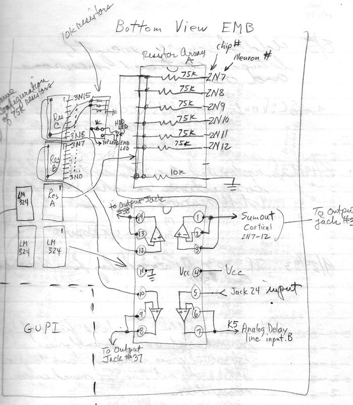
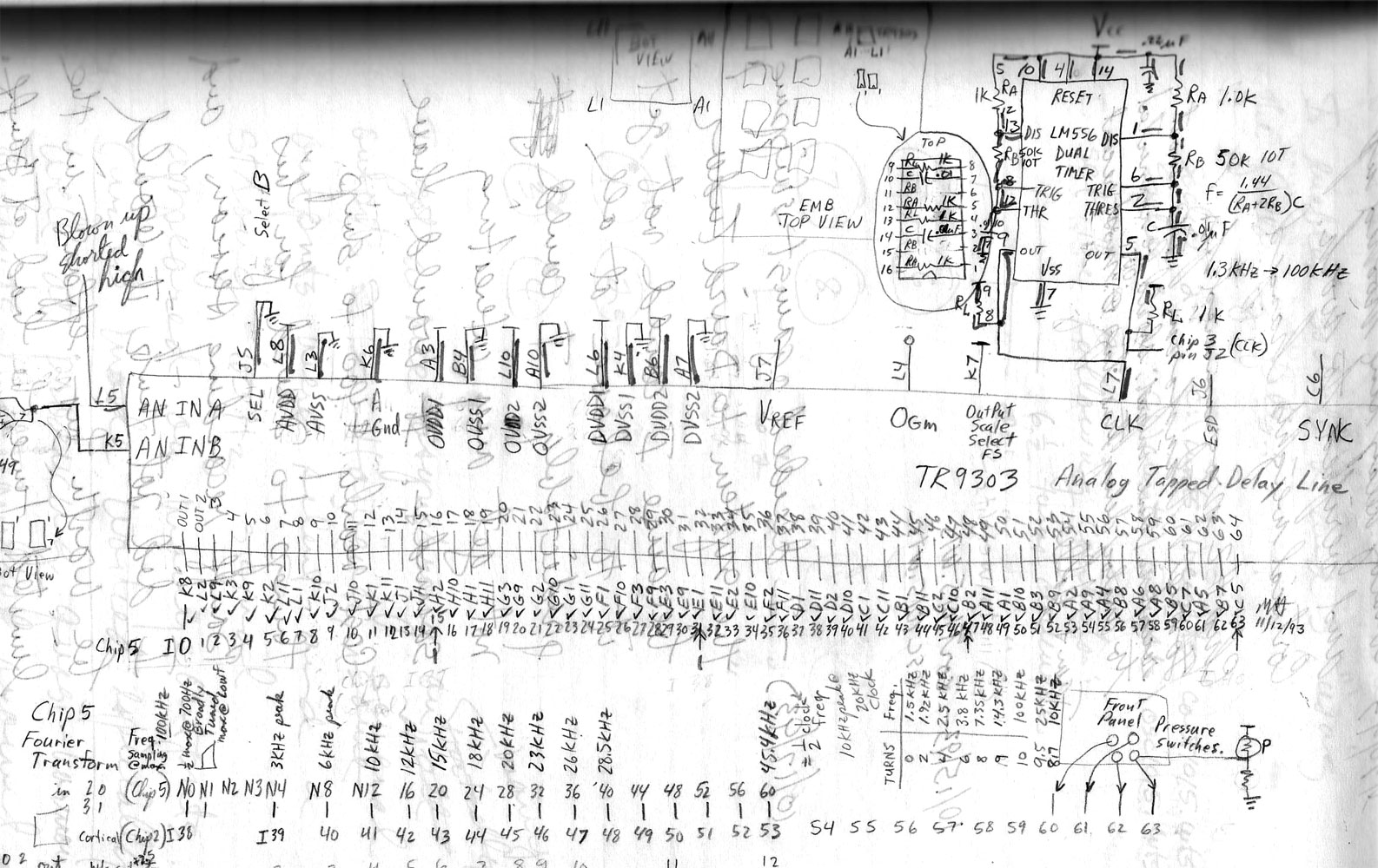
Andy Moore at CalTech developed an analog delay line chip compatible with the ETANN which is also used in MBOX II as the schematic below describes. The dot products the ETANN calculates are suitable for calculating an FFT when its inputs are driven by the taps off of an analog dealy line like Dr. Moores. The outputs of the FFT chip are connected to some of the inputs of the cortical network chip. The connection mapping is described in the diagram below. The clock for the analog delay line is generated by an LM555 timer IC and can be controlled by a potentiometer on the control panel. Adjusting this changes the frequencies corresponding to each tap that comes from the FFT chip. Higher clock rates makes the taps respond to higher frequencies as you would expect.
Still makes for some great bedtime reading.
The more you understand MBOX II the more likely it is that you will be able to get interesting sounds out of it. The general concept behind it was inspired by very loosely by human audition. Chip 3 represents the voice box. A set of general purpose single frequency oscillators that can be interconnected thickly to produce pseudo tones. Chip 2 is the "cortex", a set of spiking neurons biologically inspired that are sensitive to thermal noise which is probably the ultimate core of the perception of consciousness. Finally Chip 5's FFT and the analog delay line is something like a tone sensitive ear which outputs its spectral analysis to the cortical neurons. This is the concept behind the architecture. The result is not recognizable as any sort of autonomous, conscious entity but, it does make sounds that are unique and not reproducible in response to inputs from its environment or even with no input.
My general strategy for "playing" the box is to start with the oscillators. Turn off high gain, debias the cortical neurons and turn off the delay line clock. Turn up the gain pot and adjust the biases on the 4 neuron oscillator groups until "interesting" sounds are achieved. Then turn up the bias on the cortical neurons which will introduce spikes to the oscillations. Next turn on the feedback clock for the oscillator chip. This should make the sounds richer. You have turned chip 2 into a two layer network which brings an entire other array of weights associated with the second layer into play. At this point you will find that adding external inputs from a microphone may be desirable. If you set the biases just below threshold and then introduce sounds the sounds will "rattle around" in the feedback loops for some time before they die out or you damp them out by turning down the gain. Finally introduce an input to the analog delay line and play with its clock rate. This input can come from anywhere. I find it desirable to have a mixer's main out drive this input which gives you great flexibility to control what sound goes into the delay line at the same time you monitor the system's output. The inputs to the mixer are usually neuron outputs from both the oscillator and cortical chips as well as a microphone and wav/mp3 file sources. The mixer also allows you to listen to individual neurons without disturbing the feedback paths through the mixer. Good Luck. You will undoubtedly hear things you have never heard before when you experiment with this device. Keep your tape recorder running because you will likely never reproduce them again from the control panel.
Page by Mark Holler 11/19/07